Wednesday, July 3, 2019

Empennage Fiberglass Filling/Finishing


I've seen several aircraft flying (including the Vans owned airplane) that didn't have any filler to blend the transition from fiberglass to aluminum.  I got the idea from some other builders and we worked on this skill during the EAA course.  My desire is to have a near flawless transition between the two materials in the empennage, mainly for aesthetics, and maybe the extra .1 knots of speed due to aerodynamic effects.

I elected to use Aeropoxy products for my fiberglass work, including Aeropoxy Light which is a great filler that works very well once it's cured.  It sands very easily and smooths out nicely to provide a good base before primer.  I used a fairly thick coating in some places and then worked it down until there were no gaps.  It wasn't perfectly smooth in all places, but mainly due to slight imperfections in the glass or aluminum (e.g. waves/thickness).

I surfaced prep by sanding the aluminum and the fiberglass to ensure good bonding with the Aeropoxy.  I masked off the ares that I didn't want the filler with electrical tape.


This is what it looks like after initial application of the Aeropoxy.


And after sanding.  Very smooth.


The rudder required a lot of filler, including multiple layers.  I also added quite a bit at the forward top portion to smooth the transition between the rudder and VS.


Elevators


The bottom of the rudder presented some new challenges.  The main challenge being that the thickness of the fiberglass was thicker than where it met the aluminum.  So I had to build a little more filler on the aluminum side to aid the transition.  The second issue is that the bottom fairing on the rudder needs to be removable in order to maintain the tail position light.  I used the electrical tape on the fairing itself to prevent filler from getting on that surface.  I sanded everything with the fairing in place including the screws and am pretty happy with the results.

Here you can see where the fiberglass really sticks out above the surface of the rudder.


Empennage Fiberglass Work


After the EAA Fiberglass course, I was a little more confident to get started on the empennage fiberglass work.  However, there were still a few issues for which I was not prepared.  One is the inconsistency of the fiberglass pieces supplied in the kit.  Specifically, you can see in one of the pictures below the difference in thicknesses in some parts, especially at the flange edges.  This makes it a little more challenging to square those edges sufficiently to provide a clean and level transition from skin to the fairings.  I ended up using the edge of a sharp file to get the desired 90 degree angle and did my best to try to not take off too much material.  You can see that once the gloss coat is off the fairings, it's somewhat seethrough, but still structurally sound.


Once the VS fairing is fit, then the first mold is created that will be joined with the aft side of the fairing.  Cut slowly and work toward the final shape before sanding everything down to fit.  I used an extra layer or two of glass which did create some extra thickness that wasn't desired later on once the rudder was attached.  I would have only used two layers if I had to do it again.


Rudder fairing attached.  I used a file to take off the gloss coats in areas where I knew I would be adding Aeropoxy Light filler to fix the transition from VS to Rudder.


Elevator Fairings
 

This is the point where I realized that the rolled leading edge on the elevators wasn't correct to provide free travel during flight control movement.  I focused on the fiberglass fitting first and then fixed the shape of the leading edges later on.  Everything moves smoothly with proper distances between controls.


I didn't like the little "dip" between the rudder and the VS, so I added some filler here and am much more happy with the shape.  It was certainly a personal choice to add the time here, but I was waiting on my QB Wings/Fuselage, so definitely no hurry.


If I had this to do again, I would cut a little more off of the fairing attached to the HS.  Once the next few layers were added to the aft section of these fairings, the fit was a little tighter than I wanted it to be.  I sanded it down and (after consulting Vans) decided to back out the mounting bolts a tad to create some extra space.  This also helped with the leading edge of the elevator problem I discussed earlier.


EAA SportAir Workshops (Fiberglass for RV Builders)


January 2019

I was really lucky that EAA happened to be putting on their Fiberglass for RV Builders SportAir workshop in Las Vegas on a weekend that I just happened to be in town.  Fortunately the shop wasn't full and I was able to get some much needed instruction on how to approach the fiberglass work needed mainly in the empennage and also for the canopy.

The instructor was outstanding and had a lot of experience with fiberglass that he was willing to share with us over the two day course.  I can't say enough good things about these EAA courses.  If you think you may need the info, then attend the class.  It's well worth the cost.

We worked on several projects during the weekend, including using a form to create a fairing, fiberglass damage repair and the instructor's personal technique on blending from the canopy to the aluminum in the upper forward fuselage.


We took a 1/4" drill bit and drilled through these to demonstrate breakage.  We were then charged with fixing them.


We created these fairings from scratch using a waxed form supplied by the instructor.  It was tough to get perfectly smooth to make it look good after priming.

 
 These forms were used as the base for the aluminum to canopy transition.


Here was the final product after the instructor's unique technique for the transition.  It seems much simpler than the way that's called for in the plans and just as strong.  I think I'll give it a try when the finishing kit arrives in August '19.


Fuselage (QuickBuild)


Just like the QB Wings, a lot of the work is already complete once the QB fuselage shows up.  However, I can't stress enough the need to QC every step that they complete at the factory prior to deliver.  The ELT bracket needs to be installed and the lower gear braces need to be installed.  Those steps are buried within the earlier steps and easy to miss.

The real fun starts in Section 30, Aft Fuselage Attachment.  Prep of the aft section bulkheads is pretty straight forward.  However, getting these bulkheads into place once the aft fuselage is joined with the forward section takes a little extra time and care.  And also a rubber mallet.


I used a few sawhorses, as described in the plans, to get everything lined up.  The joining of these two pieces required two additional helpers.  One on each side at the joint, and one to lift and push near the aft part of the tailcone.  The tabs of the tailcone need to be "massaged" and lightly manipulated inside of the forward fuselage, but everything lines up well once you have the correct angle.

CAUTION:  There are temporary pop rivets in the aft part of the forward fuselage to prevent damage during shipment once leaving the factory.  If you forget to drill these out prior to trying to join the tailcone with the forward fuselage, your plight will end in tears and frustration.  Drill out these pop rivets before you get too far.  There are at least 10 of them, so look carefully at where the flush rivets end, there was usually one immediately following the flush rivet and then another in the last hole prior to the end of the skin.


I don't normally mind pop riveting, especially with a pneumatic tool, but installing the baggage floors and side panels involved a TON of LP4-3 rivets.  Wow.  I was pretty tired of leaning over the side of the fuselage by the time these were done.


Like fiberglass, I was pretty intimidated by the fuel system installation.  I've never worked with aluminum tubing nor flaring and bending of the ends.  I bought a a RIDGID 37-degree flaring tool which was very easy to use once I figured out how much of the tube to insert into the tool.  The first one I tried didn't allow the aluminum nut to get around the flare, so I had to back off a little bit.

The second issue was bending of the tubes.  The plans are pretty clear on this, but it took some time to get used to my bending tool and where the "start bend" lines needed to be in the tool to get an effective placement of the beginning of the radius.  There were enough errors in my attempts that I had to order more tubing from Vans.  I ended up getting another 6' of tubing for about $20 including shipping.  Worth the expense to make sure that I was happy with the results for such a critical system.

The longer sections of tubing that leave the selector and go to each of the wings came out well in the end.  Getting the nuts tight in the confined spaces required an 11/16" crows foot in between the sidewalls.


Here are a few of the failed attempts, which then allowed me to practice some more before more tubing arrived.


Wings (QuickBuild)


The QB wings are mostly complete upon arrival.  Fuel tanks are complete, and have been leak tested (although the plans recommend leak testing again for peace of mind).  That leaves running wiring, flight control pushrod installation and rigging, flap/aileron gap fairings and two bottom skins.  There are probably a few things I missed there, but those are the major items.


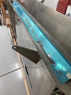
Fairings in place with vinyl still on to show general positioning.  The QB wings and fuselage are primed at the factory, so I decided to keep that trend going for the final finishing of the wings.  I used rattle can SEM self-etching primer that worked pretty well.  I applied that on both sides of the fairings and along the rivet lines for the bottom skins.  All the flight control pushrods and associated parts are primed in accordance with the plans.


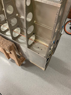
The wiring is pretty straight forward.  Just have to install the snap bushings and run the wires per the plans.  This is also where I started to get nervous about how the standard wiring harnesses will incorporate with the Stein Air or AFS panel options I'm looking into.  I guess we shall see; there's an extra unfilled snap bushing in each wing to run additional wires.  At this point I know for sure that I'll need to install a heated pitot system and that the factory included pitot placement and system will not be sufficient for my full-IFR intentions.


Riveting the bottom skins was one of the most challenging parts of the build so far.  Not so much because it's difficult to understand, just difficult to access and reach.  This is where my oldest son's assistance was crucial.  He's very good with the rivet gun at this point and I had to use my long arms to get in to the tight spaces with the bucking bar.  It took a lot of readjustments along the way and I used a lot of rags/padding to not shred my arms in the process.  I have learned many times so far that aluminum with the slightest bur cuts very efficiently.


Very happy with the final results.


Once the skins are in place, it's time to install the push rods for aileron movement.  I ensured I was spot on with the measurements for pushrod length etc. and I was pleased with the results once I had everything attached to the aileron and wing root.  Flight controls move freely and are rigged within 1/16" of the alignment jigs provided in the kit.

I purchased the LED lighting kits available at Vans.  The only problem I ran into was the connection from the standard wiring harness to the LED kits at the wing tip.  In the end, as others have done, I cut off the factory supplied connector and then attached the one that came with the lighting kit.

Total time spent on the QB wings was about 85 hours.